Switches 101
This article shows how common pedal switches work and how to figure out if they are bad or not. While the illustrations show toggle switches it also applies to footswitches. I'm going to use toggle switches to show the positions of the switches and the shaded colored areas will show what lugs are connected in each position.
Let's start off with a basic SPST switch. SPST stands for Single Pole - Single Throw. The SPST has two lugs. In one position the lugs will be connected. In the other they are disconnected. Basically a very simple on/off switch.

Next is a SPDT. Single Pole - Double Throw. This switch has three lugs. The center lug (Pole) could be considered the common lug as it's always connected to either outer lug. That is unless you have a center off switch which disconnects both outer lugs in the center position. We're just going to focus on the common on/on SPDT. In one position the center lug is connected with an outer lug and pushing the footswitch or flipping the toggle disconnects this outer lug and switches over to connect the center lug to the other outer lug.

The DPDT. Double Pole - Double Throw. This switch has six lugs. It is essentially two SPDT switches in one and switches the same as a SPDT. Each center lug is connected to either outer lug depending on what position the toggle/pushbutton is in.

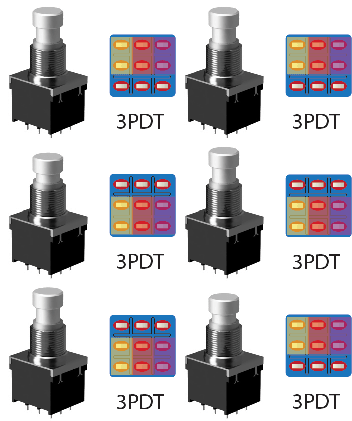
The 3PDT. 3 Pole - Double Throw. This switch has 9 lugs. It is essentially three SPDT switches in one and also switches the same as the SPDT. Each center lug is connected to either outer lug depending on what position the toggle/pushbutton is in. Here is where you have to watch out though. Because there is 9 lugs the switch could be oriented the wrong way and not work properly. Below you will see that if the switch is wired or insterted into a PCB 90 degrees wrong it won't work properly.

The 4PDT works the same as the 3PDT but it just has one more SPDT so I'm not going to go into showing how this one works.
Troubleshooting:
You will need a digital multimeter (DMM). I prefer one with a continuity buzzer but pretty much any with a diode/continuity check will work.
I'll show you how to troubleshoot the SPDT. I won't show how to do the other switches (DPDT, 3PDT, etc.) because they are just more SPDT's in one package so you just repeat this process for each set of lugs in your switch. Set your DMM on continuity/diode testing (consult your manual) and let's begin.
Position 1:

Lugs A and B should be connected while B and C should not. Touch one DMM probe on lug A and the other probe on lug B. You should have a tone if your DMM has a buzzer. Consult your owners manual to see what your DMM shows for good and open connections. If you get continuity on A and B this is good. This part of the switch is working. Now we also have to check that B and C are NOT connected. Put one probe on B and the other on C. There should be no tone or you should get a open connection. If you get continuity here, the switch is bad.
-------------------------------
Position 2:

Now let's toggle the switch so it moves into the other position as shown below. Lugs B and C should now be connected and Lugs A and B shouldn't. Place one probe on lug B and the other on lug C. If you get continuity here this part of the switch is good. Now test the other two lugs. Put a probe on lug B and the other on lug A. You should not get a tone and have a open connection here. If you don't, the switch is bad.
Now repeat this process for each set of 3 lugs/SPDT on your switch.

