
General Troubleshooting
There are a few things I do every time I troubleshoot a pedal. Usually all I ever need is a multimeter and a audio probe (shown at the bottom of this page).
First thing I do is a visual check. Is anything burnt, melted, or not looking right? Are all the wires connected? I anything out of place or odd looking at all?
If the pedal is exhibiting switching issues, I obviously look at the switch and/or switching circuit.
Then I check if the pedal is getting power to the proper places using my multimeter. Does it get power from the DC jack/battery to the main PCB? Are all the IC's getting power on their Vcc legs. If it's not, then I troubleshoot the power section. If the power section is checked/fixed and the pedal still isn't working, I move on.
Now I start narrowing down what's wrong with the audio portion of the circuit. This usually involves a audio probe and I start at the input jack and work my way through the circuit until the audio stops or I can hear where it's gone bad.
I like to break the circuit down into blocks (i.e. input buffer, gain section, tone section, out buffer, etc.) if I can to help narrow things down and not have to go through the entire circuit if I don't have to. I can listen at key points. This is where knowing how to read a schematic and translate that to a PCB comes in handy. If you don't know how to do this, take a couple hours to learn. It will make things so much easier for you.
Here are a few things to go through:
1. Check all connections that go to ground or power. Use a multimeter to verify continuity and proper voltages are present.
2. Check all of your connections, especially making sure that everything is supposed to go to ground does indeed to go ground.
3. Make sure that all points that are supposed to receive power really are getting power by looking at the connections and by measuring with a voltmeter. Connect the black lead of the voltmeter to ground of your circuit and touch the connection with the red lead of the voltmeter.
4. If you have changed a transistor or IC, double-check the orientation of the transistor or IC, make sure that the transistor or IC has the right pins in the right places.
5. Check the orientation of any electrolytic capacitors.
6. Check your resistor values throughout your circuit. It is easy to accidentally use a 470k resistor instead of a 4.7k (for example) and this could easily make a circuit not work correctly or at all.
7. With the circuit powered, measure the voltage at the battery terminal and make sure there is ~9 volts. If there are zero volts, it's possible you have a short in the circuit.
8. Very gently twist the circuit board and/or move the wiring connected to it to see if you have bad solder connections. Sometimes the circuit will spring to life because of a bad solder joint and this can help to show if you do or not.
9. If you are testing the board in the enclosure and it worked while it was out of the enclosure, look for any place the enclosure or a pot or stray wire might be touching the board or a wire and grounding out the circuit.
10. Make sure when you put the pedal back together that the Pots lugs do not touch other pots or the case.
11. If you are still having problems at this point, make an Audio Probe (see below) and trace through the circuit. You should have one anyway if you are building and modifying pedals. Build it, use it, and it will make things so much easier to fix.
The Audio Probe:
You can use a audio probe to start at the input jack tip and follow the circuit through to the output jack tip. You will want to follow the audio path and this is where a schematic comes in handy. Sometimes I find it easier to break a circuit down into sections (i.e. input buffer, gain stage, tone section, output buffer, etc.) so it's easier and faster to narrow down the issue.
Solder Joints:
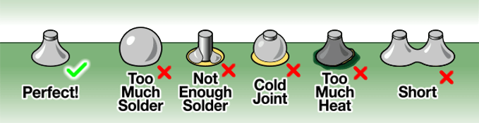
Check your solder joints. They should be conical and smooth. Not meteors or balls and you shouldn't be able to see through the solder pad to the other side. Take your time when you solder and make good solder joints. Check the one you just did before moving onto the next and fix it if it's not good. It only takes one bad solder joint to mess things up. It may take longer but it's a lot easier than troubleshooting.
Symptoms and things to check:
I have bypass signal but when I turn the pedal on there is no sound :
This is in no way a sign of the actual circuit working or not working. If you get bypass signal, you most likely have the input and output jacks wired correctly. Problem may lie in the switch. Either it's bad, wired wrong, or you have a cold solder joint on it.
I don't get a bypass signal or any signal when the pedal is on:
You may have wired the input/output jacks or the switch wrong.
My pedal doesn't work but my LED lights up:
The LED typically operates independently from the rest of the circuit. Meaning, a LED lighting up really only means you have power going to the LED. If the LED is on the main PCB, it could be a indicator that you at least have power to the PCB but I would still check. If power is getting to the board then I would go through it with a audio probe.
My pedal works but my LED doesn't light up:
The LED typically operates independently from the rest of the circuit. Meaning, a LED lighting up really only means you have power going to the LED. If it's not lighting up you may have installed it wrong. It's a polarized component so it will only work one way. Check the orientation. If the orientation is correct, you can use a multimeter to check if it's getting voltage. If it isn't or it's very low you'll have to follow the circuit from the LED to the power section to find out why.