
Components - Potentiometers/Trimmers
Potentiometers and Trimpots 101
This page is a work in progress.
Potentiometers (also known as a pot) and trimpots (also known as a trimmer) are three terminal resistors with a rotating or sliding contact which form a adjustable voltage divider. There are multi-gang pots, ones with switches, etc. but we'll start with a basic single gang potentiometer.
Below is a animation of a potentiometer. Trimpots have the same construction so pretty much everything succeeding this applies to trimpots too. There are three terminals in which I labeled A, B, and C. A and C are the outer terminals which connect to the resistive strip/carbon track. B is the terminal that connects to the wiper. The wiper is rotated by turning the shaft of the potentiometer. Typically when you see a potentiometner/trimpot labeled it would be legs 1, 2, and 3 with lug 1 on the left, 2 in the middle, and 3 on the left with the pot shaft facing you. I went with A, B, and C because R12 and R23 looked confusing.
As the wiper moves towards a outer terminal, the resistance on that terminal gets lower. Concurrently, as the wiper is moving away from the other outer terminal, the resistance on this other outer terminal increases. In the animation you can see that as the wiper moves towards terminal A (CCW - Counter Clockwise), the resistance between terminals A and B (RAB) decreases while the resistance between terminals B and C (RBC) increases. As the wiper moves towards outer terminal C (CW - Clockwise), resistance RAB increases and the resistance RBC decreases. There is also a animated potentiometer schematic symbol next to the potentiometer that shows this increase and decrease of resistance in relation to the wiper position. You may noticed I used the terms CW and CCW which is clockwise and counter clockwise. You may see these terms when looking at schematic symbols. These help determine the potentiometer orientation.
Measuring A Potentiometer:
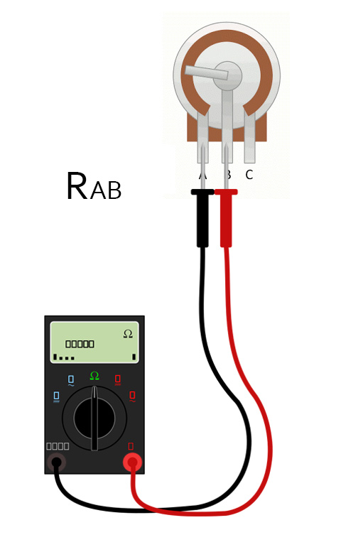
When you measure a potentiometer, you measure two legs at a time using a multimeter. The resistance (measured in Ω) shown on the multimeter will depend on where the wiper is located along the resistive strip.
First thing you want to do is set your multimeter to the ohms setting. Not all multimeters are the same. Some are auto ranging and some you have to pick a appropriate ohms range for the component you are measuring. For instance, if you are measuring a 100KΩ potentiometer, you would want to pick a ohms range above 100KΩ. Consult the owners manual for your meter.
Moving on, to measure the resistance RAB you would put the probes on terminals A and B. Doesn't matter which probe on which terminal in these measurements. The resistance on your meter should alter as you rotate the potentiometer shaft. Turning it CCW should lower the resistance to 0Ω while turning it CW should increase the resistance to the full potentiometer value.
A little side note here. Components have something called a "manufacturing tolerance". This is a minimum and maximum tolerance permitted between the design/stated value and actual product. Potentiometers can have a manufacturing tolerance of +/-20% so that means a 100KΩ pot may measure anywhere from 80KΩ to 120KΩ when turned to full resistance.
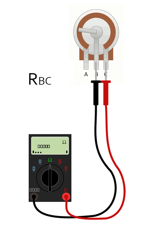
To measure the resistance of RBC you put the probes on terminals B and C. Again rotating the shaft will alter the resistance shown on your meter.
 |
 |
Tapers:
Wiring A Potentiometer As A Variable Resistor-Rheostat:
Altering A Potentiometers Value:
Digital Potentiometer: